- Oct-25-2023 - Compile Times and Code Graphs
- Oct-26-2023 - Thread per core
- Oct-27-2023 - Introducing Glommio
- Nov-01-2023 - Why Async Rust
- Nov-05-2023 - Are You Sure You Want to Use MMAP in Your Database Management System?
- Nov-06-2023 - Log Structured File Systems
- Nov-14-2023 - Flash Based SSDs
- Nov-15-2023 - The Unwritten Contract of Solid State Drives
- Nov-20-2023 - HDFS Architecture
- Nov-30-2023 - Bumper Sticker API Design
- Dec-04-2023 - HTTP/3: the past, the present, and the future
Oct-25-2023
Title: Compile Times and Code Graphs
Having an ideal code dependency structure improves compile times by reducing the number of units that transitively depend on the unit that gets a code change.
The ideal structure looks like:
- A base layer of a small number of foundational crates that are mostly stable.
- A middle layer that fans out to implement various business logic.
- A top layer that produces a few binaries by fanning in the middle layer.
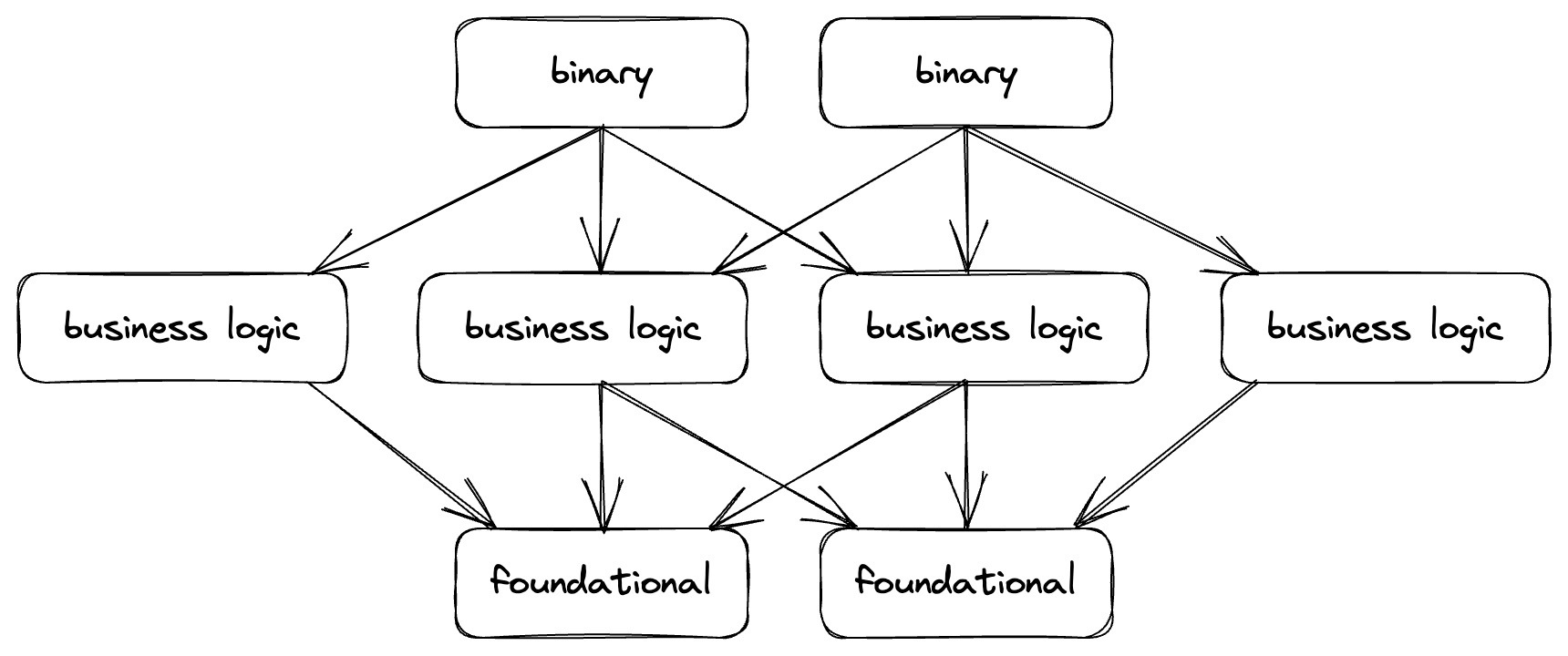
In terms of concretely implementation this structure results in:
- A base layer of core types, protobuf definitions etc.
- A middle layer of traits describing interfaces/services.
- A top layer implementing interfaces and services.
Oct-26-2023
Title: Thread per core
What are the tradeoffs between having a thread-per-core (shared nothing) arch versus a multi threaded with work stealing.
Thread per core combines three big ideas: (1) concurrency should be handled in userspace instead of using expensive kernel threads, (2) I/O should be asynchronous to avoid blocking per-core threads, and (3) data is partitioned between CPU cores to eliminate synchronization cost and data movement between CPU caches. It’s hard to build high throughput systems without (1) and (2), but (3) is probably only needed on really large multicore machines
_ source _
Shared-nothing arch has been demonstrated to be performant than traditional shared-state arch. However, shared-nothing requires data partitioning which is harder than passing mutexes in shared-state arch.
Due to real life load imbalance (e.g. hot keys) some threads in the shared-nothing arch will perform more work than others. The raison d'etre of work stealing is to redistribute some of the work from busy threads to idle threads. This however introduces synchronization and cache misses.
There are clear reasons for both approaches, the correct approach seems to be determined by the load patterns.
Oct-27-2023
Title: Introducing Glommio
#rust
Glommio is an async runtime by Datadog implemented using the thread-per-core shared-nothing paradigm.
Sharding is necessary to implement thread-per-core, it partitions the keyspace to the various threads. Also since only a single thread operates on a shard, there's no need for locking; even if there might be several async tasks on the same thread their data access will be serialized.
Glommio provides a task queue mechanism that allows to define latency requirements and execution time requirements. Tasks can then be queued based on their needs e.g. if long running and not latency sensitive etc.
Glommio uses io_uring; Linux's new async IO API. It has three rings: main, latency and poll. The latency ring exists in order to prioritize latency-sensitive task !? I'm not sure, it wasn't clear to me.
Thread-per-core is possible in k8s if you:
- Avoid oversubscription of resources
- Assign pods to specific nodes
- Limit pods to specific CPUs
- Isolate hardware interrupts, so they are outside the pod
Nov-01-2023
Title: Why Async Rust
#rust
This is an overview of why the async concurrency model exists the way it is today in rust.
Rust has a stackless coroutine implementation using state machines and has cooperative scheduling. A coroutine is a function which can be paused and then later resumed
Rust’s async/await syntax is an example of a stackless coroutine mechanism: an async function is compiled to a function which returns a
Future, and that future is what is used to store the state of the coroutine when it yields control.
Rust experimented with green threading (a stackful coroutine mechanism) but abandoned it coz:
- green threads stack management has overheads. For both segmented stack and stack copying approaches.
- Stack copying boils down to a garbage collected approach which isn't feasible in Rust since there's no GC.
- There's a huge cost for FFI - when integrating with other languages.
Rust async programming has a "readiness-based" approach where a future is driven by an external executor. The future wakes the executor when it's ready. This external execution approach is very similar to how iterators are implemented - an "external" struct holds the state of iteration and references to the actual data structures being iterated over.
Iterator trait:
trait Iterator {
    type Item;
    fn next(&mut self) -> Option<Self::Item>;
}
Future trait:
enum Poll<T> {
    Ready(T),
    Pending,
}
trait Future {
    type Output;
    fn poll(&mut self) -> Poll<Self::Output>;
}
Future combinators require access to the future's state across await points. Pinning via the Pin type solved this by guaranteeing that a future won't move in memory and therefore is safe to have internal references.
Nov-05-2023
Title: Are You Sure You Want to Use MMAP in Your Database Management System?
#databases #filesystems #linux
I have been reading up on mmap and came across this paper. It covers correctness and perf issues that using mmap brings and how it's a terrible idea to use it. The paper focuses on DBMSes but I think the issues apply to a broader context.
What is mmap?
Memory-mapped (MMAP) file I/O is an OS-provided feature that maps the contents of a file on secondary storage into a program’s address space. The program then accesses pages via pointers as if the file resided entirely in memory. The OS transparently loads pages only when the program references them and automatically evicts pages if memory fills up.
In DBMSes it seems like a great substitute for buffer bools; an in-memory cache of pages read from disk.
What makes mmap attractive?
- OS manages file I/O for the application. App does not deal with low-level page management.
- mmap avoids data copying to userspace as application can directly access data in OS page cache. This should be more performant than normal file I/O.
How mmap works?
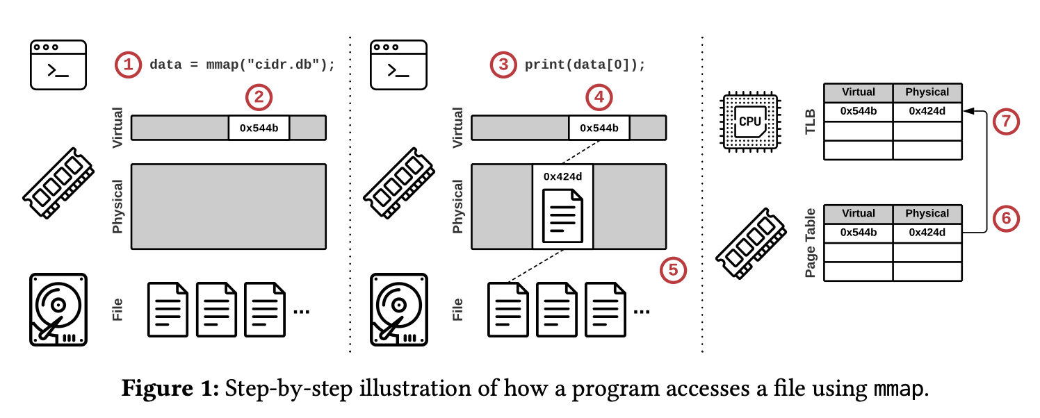
- A program calls mmap and receives a pointer to the memory-mapped file contents.
- The OS reserves part of the program’s virtual address space but does not load any part of the file.
- The program accesses the file’s contents using the pointer.
- The OS attempts to retrieve the page.
- Since no valid mapping exists for the specified virtual address, the OS triggers a page fault to load the referenced part of the file from secondary storage into a physical memory page.
- The OS adds an entry to the page table that maps the virtual address to the new physical address.
- The initiating CPU core also caches this entry in its local translation lookaside buffer (TLB) to accelerate future accesses
Why mmap sucks? 💩
- Transaction safety
- Since OS performs transparent paging, it can flush dirty pages to disk anytime. This is an issue for apps that perform transactions and need to control when updates are committed.
- I/O stalls
- When a page fault occurs, mmap performs blocking I/O to fetch page from disk. mmap does not support async reads.
- Error Handling
- For apps that perform data integrity checks e.g. using checksums, mmap makes it hard due to transparent page loads/evictions. There's no way to know if a page changed.
- mmap I/O errors are more complicated to handle.
- Perf Issues
- page table contention
- single-threaded page eviction
- TLB shootdowns: occur during page eviction when a cpu core needs to invalidate mappings in a remote TLB. Whereas flushing the local TLB is inexpensive, issuing interprocessor interrupts to synchronize remote TLBs can take thousands of cycles
- Other
- If the mmap is shared, contention on the mmap write lock leads to poor perf.
- mmap is more expensive than read sys call for SSDs.
- mmap implementations across platforms are not compatible. windows vs linux vs darwin
- Since the OS manages the file mapping, the in-memory data layout needs to match the physical representation on secondary storage, leading to wasted space and reduced I/O throughput. Notably no compression can be performed for data on disk.
Nov-06-2023
Title: Log Structured File Systems
#lfs #filesystems #ostep
A chapter in the OSTEP book.
The basic idea of LFS is all updates are written to disk sequentially to an append only log data structure. LFS never overwrites existing data, it writes data segments to free locations.
How is good write perf achieved?
Using write buffering. The LFS tracks updates in memory and when there's a sufficient number of updates, it will write them sequentially to disk. This provides efficient use of disk bandwidth. A good buffer size can be determined using this equation:
D = (F/1-F) x Rpeak x Tpos where:
- D - buffer size in MB
- F - effective rate between 0 and 1 corresponding to desired efficiency; 0.9 => 90%
- Rpeak - data transfer peak rate in MB/s
- Tpos - disk seek time to certain position
How do you track file inodes in LFS?
LFS introduces an inode map structured for this. It maps the inode number to a disk address with the most recent version of the inode. LFS stores chunks of the inode map next to the data blocks on the log. It then uses fixed addresses on disk (checkpoint regions) to store pointers to the latest pieces of the inode map.
How is a data read from a file?
The algorithm is simple:
- Read checkpoint region
- Read entire inode map and cache it memory (for subsequent reads)
- Look up the file's inode and get it's address on disk
- Read data block from file.
Garbage collection
LFS has to clean old versions of files that have been replaces by newer versions. LFS implements a cleaner that reads in a number of old (partially-used) segments, determines which blocks are live within these segments, and then write out a new set of segments with just the live blocks within them, freeing up the old ones for writing.
It uses a segment summary block to store info used to decide whether a data block is live or stale. It basically keeps the inode version of the file in the summary block and check if the inode is still the current one in the inode map. If the inode map returns a different inode then the data block is stale and can be garbage collected.
When and which blocks to clean?
The when is simple:
- periodic
- during idle time
- when disk is full Which blocks to clean is harder:
- based on policies / heuristics
- hot/code segments approach: do not GC hot segments regularly since the keep changing.
Crash recovery
How to recover when system crashes as LFS is writing to disk?
- by carefully writing checkpoint regions
- uses timestamps in CR's head and tail.
- detects crashes by checking timestamps
- recovery starts at last CR and uses the roll forward technique
Nov-14-2023
Title: Flash Based SSDs
#ssd #ostep
Another chapter in the OSTEP book.
Flash chips are designed to store one or more bits in a single transistor; the level of charge trapped within the transistor is mapped to a binary value. In a single-level cell (SLC) flash, only a single bit is stored within a transistor; with a multi-level cell (MLC) flash, two bits are encoded into different levels of charge.
A flash chip consists of many banks, each of which is organized into blocks. Each block is subdivided into pages. Blocks are large (128KB–2MB) and contain many pages, which are relatively small (1KB–8KB).
To read from flash, issue a read command with an address and length; this allows a client to read one or more pages. Writing flash is more complex. First, the client must erase the entire block. Then, the client can program each page exactly once, thus completing the write.
A flash-based solid-state storage device (SSD) behaves as if it were a normal block-based read/write disk; by using a flash translation layer (FTL), it transforms reads and writes from a client into reads, erases, and programs to underlying flash chips. An in-memory translation layer tracks where logical writes were located within the physical medium.
Challenges with SSDs:
- wear out: when a flash block is erased and programmed, it slowly accrues a little bit of extra charge. Over time, as that extra charge builds up, it becomes increasingly difficult to differentiate between a 0 and a 1. At the point where it becomes impossible, the block becomes unusable. Flash reliability is mostly determined by wear out; if a block is erased and programmed too often, it will become unusable.
- disturbance: When accessing a particular page within a flash, it is possible that some bits get flipped in neighboring pages; such bit flips are known as read disturbs or program disturbs, depending on whether the page is being read or programmed.
Most FTLs are log-structured, which reduces the cost of writing by minimizing erase/program cycles.
Key issues with log-structured FTLs:
- the cost of garbage collection, which leads to write amplification. The trim operation is useful to tell the device when particular blocks are no longer needed.
- the size of the mapping table, which can become quite large. Using a hybrid mapping or just caching hot pieces of the FTL are possible remedies.
- wear leveling; the FTL must occasionally migrate data from blocks that are mostly read in order to ensure said blocks also receive their share of the erase/program load.
Nov-15-2023
Title: The Unwritten Contract of Solid State Drives
#ssd
A set of rules that SSD clients should follow to obtain high perf.
-
Request Scale.
Clients should issue large requests or many requests in order to exploit the internal parallelism of SSDs. Log structures techniques naturally exploit this parallelism. OS-driven buffered reads throttles disk IO, direct IO achieves better scaling.
-
Locality
Clients should access data by locality in order to reduce translation cache misses in the Flash Translation Layer (FTL). Locality is improved by space reuse.
-
Aligned Sequentiality
In order to reduce the cost of converting page-level to block-level mappings in FTL, clients should start writing at the aligned beginning of a block boundary and write sequentially.
-
Grouping by Death Time
Writes should be grouped by their likely time of death in order to reduce the cost of garbage collection. If an entire block is dead, the GC only erases the block and doesn't have to rewrite data elsewhere.
-
Uniform Data Lifetime
Clients should create data with similar lifetimes to reduce the cost of wear-leveling.
Nov-20-2023
Title: HDFS Architecture
#distributed-systems #filesystems #hdfs
The Hadoop Distributed File System (HDFS) is a distributed file system designed to run on commodity hardware. It's designed to be highly fault tolerant, have high read throughout and support large files.
Assumptions and Goals
- Hardware failure: Hardware failure is the norm rather than the exception. Detection of faults and automatic recovery is a core goal.
- Streaming data access: Applications that run on HDFS need streaming access to their data sets.
- Simple Coherency Model: HDFS applications need a write-once-read-many access model for files.
- Moving computation is cheaper than moving data: A computation requested by an application is much more efficient if it is executed near the data it operates on.
- Portability: HDFS has been designed to be easily portable from one platform to another.
Architecture
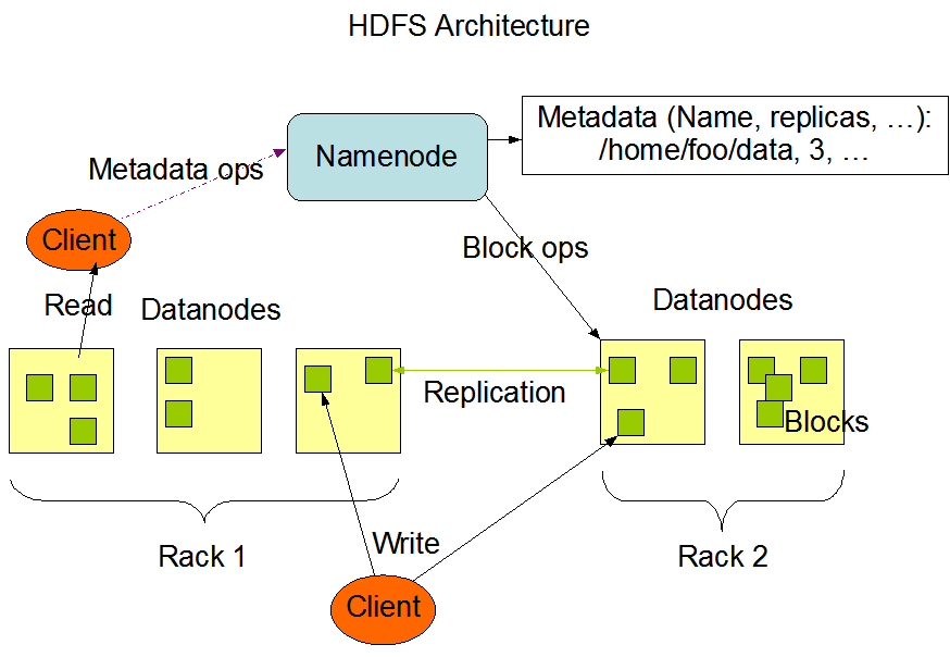
HDFS has a controller/worker architecture. A single NameNode (controller) server that manages the file system namespace and regulates access to files by clients. A number of DataNodes (worker), usually one per node in the cluster, manage storage attached to the nodes that they run on.
Data Replication
HDFS stores each file as a sequence of blocks. The blocks are replicated for fault tolerance. The block size and replication factor are configurable per file. All blocks in a file except the last block are the same size.
An application can specify the number of replicas of a file. The replication factor can be specified at file creation time and can be changed later. Files in HDFS are mostly write-once and have strictly one writer at any time.
The NameNode makes all decisions regarding replication of blocks. It periodically receives a Heartbeat and a Block report from each of the DataNodes in the cluster. Receipt of a Heartbeat implies that the DataNode is functioning properly. A Block report contains a list of all blocks on a DataNode.
Data Replication involves:
- Replica placement: determines to where (in which data nodes) data is replicated. HDFS has a rack-aware replica placement policy to improve data reliability, availability, and network bandwidth utilization. By default the replication factor is 3; two replicas are on different nodes of one rack and the remaining replica is on a node of one of the other racks.
- Replica selection: To minimize global bandwidth consumption and read latency, HDFS tries to satisfy a read request from a replica that is closest to the reader.
- Block placement: similar to the replica placement.
- Safe mode: The NameNode has a safe mode (usually at startup) in which it:
- Receives block reports from data nodes: A Block report contains the list of data blocks that a DataNode is hosting.
- Check that each data block has the minimum number of replicas.
- Replicates missing data blocks, if any.
File system metadata.
This is handled by the NameNode. It uses a transaction log (EditLog) to persistently record every change that occurs to file system metadata. The entire file system namespace, including the mapping of blocks to files and file system properties, is stored in a file called the FsImage.
During startup, the NameNode reads the FsImage and EditLog from disk, applies all the transactions from the EditLog to the in-memory representation of the FsImage, and flushes out this new version into a new FsImage on disk. It can then truncate the old EditLog because its transactions have been applied to the persistent FsImage. This process is called a checkpoint.
Nov-30-2023
Title: Bumper Sticker API Design
#api-design
A set of maxims on good API design:
Documentation
- API should be self documenting.
- Document every exported API element: every class, method, field, and parameter.
Flexibility
- Gather requirements with skepticism - you have to find out the underlying problems.
- Early drafts should be concise - makes it easy to refactor later.
- Avoid fixed limits on input sizes.
- Keep API free of Implementation details.
Testing
- Write use cases against your API before implementing it - don't implement wrong API.
- Maintain code for use cases as API evolves.
- Structure requirements as use-cases.
Principles
- Least astonishment - every method should do the least surprising thing it could, given its name.
- Fail fast - the sooner you report a bug, the less damage it will do.
- Easy to use and hard to misuse - easy to do simple things, possible to do complex things, hard to do wrong things
- Names matter.
- When in doubt, leave it out.
- Exceptions are for exceptional conditions.
- Its art, not science - strive for beauty.
Dec-04-2023
Title: HTTP/3: the past, the present, and the future
#http #quic #rust
A look at the evolution of HTTP and it's future with QUIC and HTTP/3.
Each revision of the HTTP protocol tries to solve problems of the previous revision.
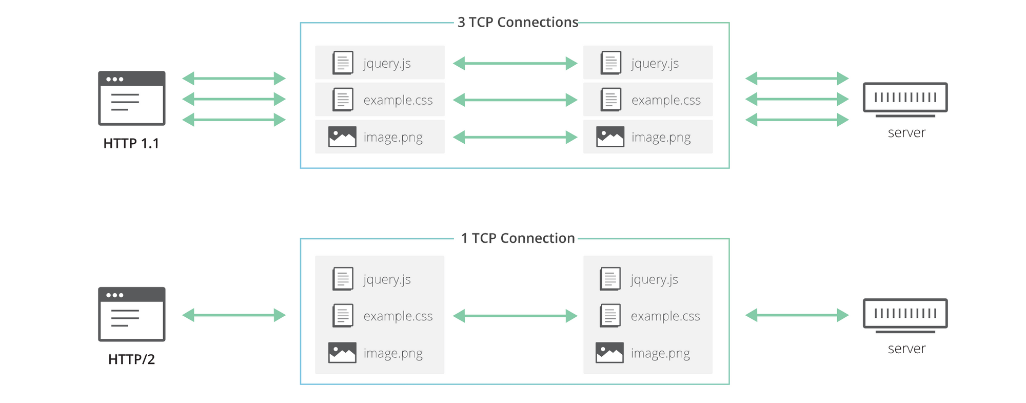
HTTP/1.1 introduced keep-alive connections to allow clients to reuse TCP connections and thus amortize initial connection setup costs. This reuse wasn't possible in 1.0.
HTTP/2 introduced streams, an abstraction that allows implementations to concurrently multiplex different HTTP exchanges onto the same TCP connection, allowing browsers to be more efficient.
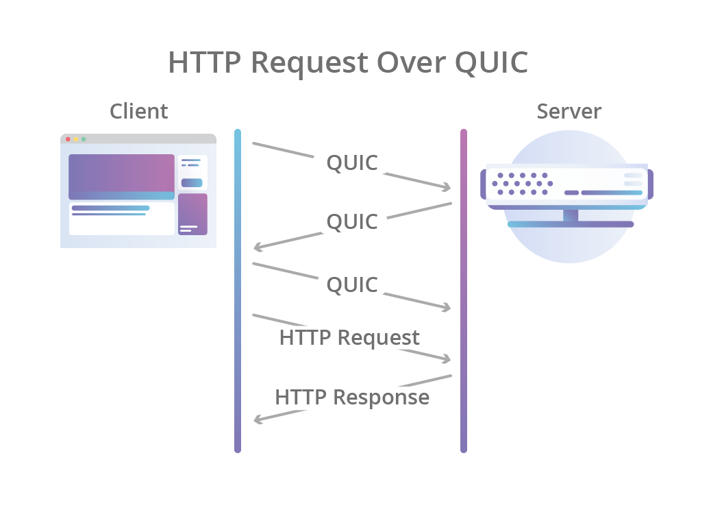
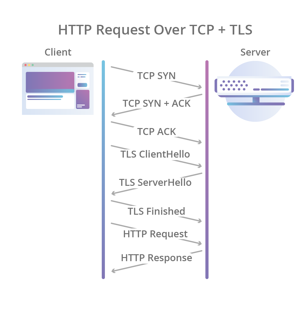
HTTP/3 improve streams by making them first class citizens at the transport layer using the QUIC transport protocol. It eliminates the head-of-line blocking problem in HTTP/2. QUIC streams share the same QUIC connection but are independent and packet loss on one stream does not affect the rest.
QUIC also merges the TCP handshake with the TLS 1.3 handshake, making encryption and auth to be provided by default and enabling faster connection establishments.